Reference documents #
Arduino MKR wifi 1010 schematic
Arduino MKR Wifi 1010 hardware overview #
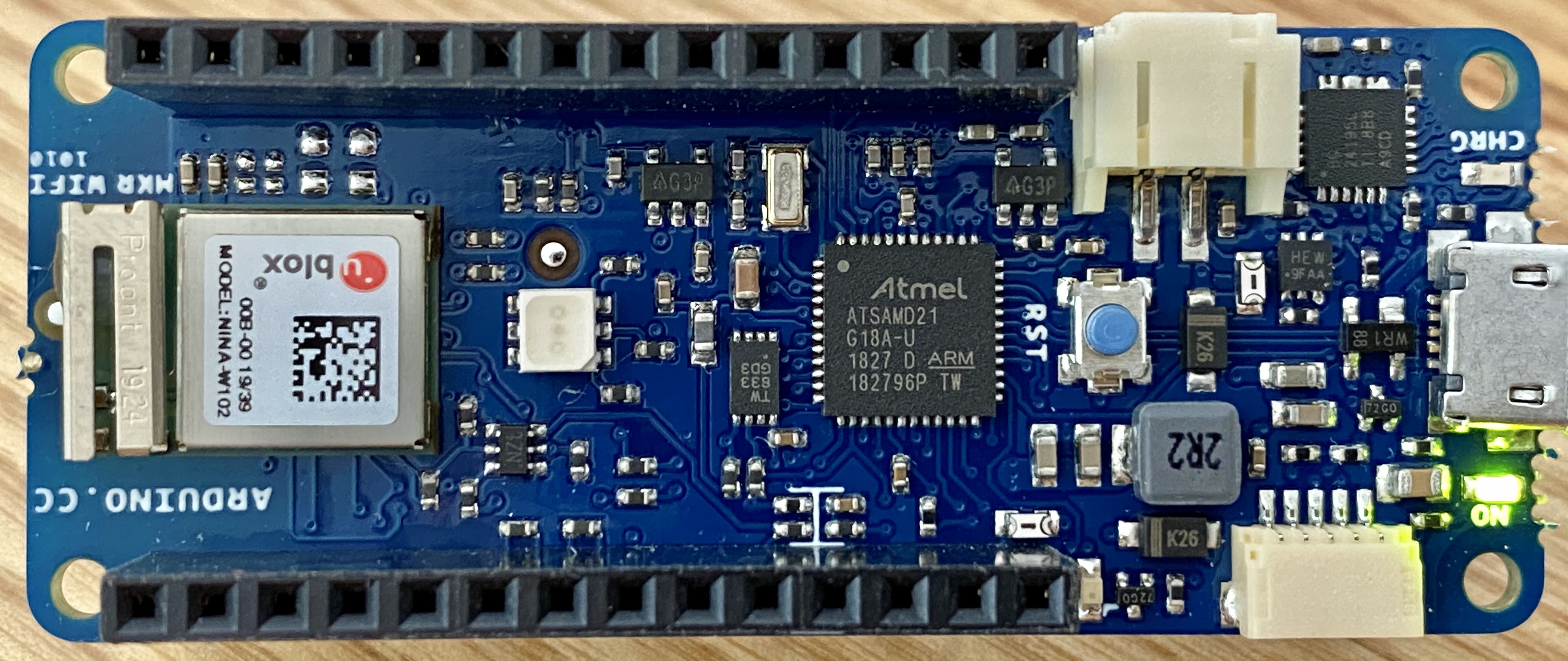
Looking at the picture above, you can see three large chips, some connectors, and a lot of tiny resistors and capacitors. Right in the middle is the microcontroller that acts as the brain of the board. It’s an Atmel ATSAMD21G18A-U, which is an ARM Cortex M0+ running at 48 MHz. The 1827 code on the chip means that this particular chip it was manufactured in week 27 of 2018.
At the left edge of the board, you can see the uBlox NINA W102 module, which is what provides the wifi and Bluetooth connections to the board. This is an Espressif ESP32 microcontroller inside a metal box with a small wifi antenna next to it. Its main advantage is that the module has passed FCC 47 CFR 15 certification, so the Arduino folks can add it to their board without having to go through the tedious and expensive certification process required of everything with a radio transmitter.
At the right edge of the board is the Texas Instruments BQ24195L battery management chip. It watches the USB and battery connectors for power sources and, when both are connected, passes current from the USB port to the battery at the right voltage to charge the battery. The L at the end of the part number indicates that it’s a low-current part that can supply only 1.0 A from the battery back to the USB port, rather than the 2.1 A available with the plain BQ24195.
There’s one mysterious chip on the board, just to the left of the microcontroller. It has 8 pins and is labeled TW 833 GD3. According to the schematic, the board has an ATECC508 crypto chip on it. Curiously, the ATECC508 datasheet says that, “As part of Microchip’s overall security features, the part mark for all crypto devices is intentionally vague.The marking on the top of the package does not provide any information as to the actual device type orthe manufacturer of the device.”
However, the first Google image search result for “TW 833 chip” is an Adafruit board that mentions an ATECC508 device. Hmmm.
Connectors #
The right end of the board has three different connectors. The white, 2-pin connector at the top, right next to the battery chip, is a JST connector for a 1-cell lithium ion battery. The silver connector on the short side of the board is a micro USB connector for communication with a host computer. The white, 5-pin connector at the bottom of the board connects to the I2C bus of the M0+, as well as an extra digital pin, power, and ground.
Learning to program your Arduino #
Arduino’s Tutorials are a great resource for Arduino newcomers. We urge you to spend time walking through this resource.