Projects #
P6: Build something useful #
You’re now a reasonably competent embedded systems engineer. Design and build something that solves a problem in the world. It should be either hardware that plugs into or contains a microcontroller, or code that runs on a microcontroller, or a combination of the two. If you lean toward software, your project could be as simple as a test suite for an open source Raspberry Pi library. If you lean toward hardware, it could be as simple as a breakout board for a newly-released sensor. The main point is that you should think of something that is interesting to YOU.
If you want to expand your range, you can work in teams of two, where one of you focuses on hardware and one of you focuses on software. In this case, you should aim to complete something roughly twice as ambitious.
If you decide to make a PCB, it should definitely be submitted to the manufacturer by the project deadline, but it need not arrive back by then.
P5: Pi Pico PIO pioneering #
(WELCOME TO P5 2.0! NOW WITH MORE REALITY!)
Your mission in P5 is to gain some experience with the Raspberry Pi Pico’s PIO subsystem.
- Option 1 Write a PWM controller that runs on the Pico and allows only smooth acceleration. Your code should use the PIO hardware to output a PWM signal. You can limit acceleration in your Python code (as it appears to be impossible to do it in the PIO state machine). Connect your Pico to a small DC motor and a MOSFET and make a short video demonstrating smooth operation vs. jerky operation. (Nolop will have MOSFETs and a small motors if you don’t have them.)
Some calculus review: we call the first derivative of position “velocity,” the second derivative “acceleration,” and the third derivative “jerk.” Consider a robot arm where the motors controlling the joints can change acceleration rapidly– this is an arm that moves jerkily. In some cases, that’s fine, but what if we want smooth motion? You can keep track of the acceleration and only allow it to change slowly, thereby enforcing smooth motion.
If you’re feeling advanced, you could also linearize the PWM vs. speed curve, so that an N% duty cycle gives you N% of your top speed. Without this, your motor probably doesn’t actually start spinning until 10-20%, and then gets very close to top speed around 80%.
A few other notes: you should probably do this in Python. Note that Micropython and Circuitpython deal with the PIO hardware differently, so use Micropython unless you have a good reason to switch.
- Option 2 Write some more ambitious PIO hardware program that you’ve been wanting to try ever since you heard about this PIO thing back in January.
P4: Pico: Endgame #
For P1, you made a PCB for a Pico accessory. In P4, your task is to refine your device.
In most of the project work you do in school, you make something, submit it for grading, and then throw it in the trash. The goal of this project is to give you a chance to do deeper learning, by reviewing the work that you’ve done and taking another cut at improving it.
There are, however, a few options:
- Option 1: your P1 project was satisfying for you. Great! Make it better. If your PCB is flawless, make a smaller version and a beautiful enclosure for it. Write whatever code needs to be written to make it work. If you want, create a documentation website on Github. If you do that, make 10 and start selling them on Tindie. I will buy one.
- Option 2: your P1 project was more of a PCB test project for you. Great! Make a new PCB that will do something even better.
- Option 3: you’re just not that into hardware. Great! Write an open source library for the Pi, the Pico, or another popular microcontroller and publish it on Github. If you want, create a documentation website too. Your library should help people do something that you think is useful.
P4 Milestones #
There are two milestones for P4: a brief project proposal and a final submission. You must do both of them.
- Before class on Tuesday, March 16, DM me a 1-3 sentence description of what you intend to do. I will either reply, “Approved!” or give you a few suggestions about how to tweak your proposal, if you’ve misunderstood the project requirements, or I have some confusing parts in this project description. The point of this milestone is just to get you to commit to a plan early.
- Before class on Thursday, April 1, submit documentation of your project, similar to P1, on Canvas. Screenshots are fine.
One more note: it would be a really good idea to assemble your PCB from P1 to validate your initial design decisions and discover any problems. You can get stuff soldered via the #soldering channel in the Nolop Slack.
P3: Use your Pi computer for actual computation #
Throughout engineering school, you learn to create mathematical models in a variety of different domains: heat transfer, fluids, dynamics, mechanics, and so forth. In school, we often use these models to solve a unique problem with known parameters: “If I have a flat plate at 25 C of these dimensions and I pour N watts into one edge with a torch, how long until the far corner reaches the boiling point of tears?”
In professional practice, we do the same thing, but we often have a lot less certainty about the input parameters than the problems you find in textbooks. This means that we need to execute our calculations repeatedly, and we often want to do that as fast as we can. This is when we use computers.
The project has two parts:
- Week 1: Pick an engineering problem and solve it on your Pi in Python. Measure how long it takes your code to find the solution.
- Week 2: Make your code run faster. If you can hit 100 times faster, create a sensitivity analyis, where you sweep your solution across a range of possible inputs and create a visualization of how the result changes.
- (Optional: create a web-based interface that graphs your results on the Pi.)
A few other notes:
- Pick a problem that you have some idea how to solve, not some insanely impossible thing. A final exam problem from your favorite class last semester would be a good choice. The problem does not have to be from a class. Something with a differential equation that you can solve numerically would be a good target.
- You should write your first version in Python. After that, use whatever language you want (more Python, C, Cython, Julia, or even Javascript).
- The goal here is to get you some exposure to scientific computing, some experience with using a mathematical model to reach a real solution, and possibly some appreciation for the value of numerical solutions in our era of fast, cheap computation.
- You might need to do some research to execute this project. There are lots of different ways to optimize the performance of your code; this project is not simply, “Write the code and then click the button labeled 100x in the IDE.” (It would be cool if that button existed.)
- Because you will likely have multiple versions of your code as you complete the project, this would be a great opportunity to use git/Github as a version control tool.
P2: Program an oscilloscope puzzle for the Pico #
ME 30 is the electronics course that every mechanical engineering junior takes at Tufts. Next year, it will have a new challenge called “the oscilloscope puzzle.” The goal is to teach ME 30 students how to use an oscilloscope, which is a device that measures voltage like a multimeter, but shows you a graph of voltage over time, rather than just a single instantaneous reading. The ME 30 students, hereafter called “the detectives,” will have to use an oscilloscope to find signals on the Pico’s pins, interpret them, and then follow whatever directions they find to advance through the puzzle.
There’s another goal too, which is to get you all to learn how to program a Pico, and especially how to implement a state machine.
I created the original version of this back in 2017 for an EN 1 course, but it had a fundamental problem, which is that once one detective solves the problem, the secret is out. Now, with the 32 of you, we can make 32 different puzzles that appear the same from the outside, but have different solutions. Your brain is like the salt in our password hash.
A few detailed requirements:
-
The puzzle should have 4 states: ONE, TWO, THREE, and SOLVED. During the numbered states, the Pico’s onboard LED should blink as many 100 ms pulses as the state name every 1 second, so the detectives can track what state they are in.
-
Here’s some ASCII art that shows what the pulses should look like. Each asterisk is a 100 ms pulse; each underscore is a 100 ms gap.
STATE ONE:    *_________*_________*_________
STATE TWO:    *_*_______*_*_______*_*_______
STATE THREE:  *_*_*_____*_*_*_____*_*_*_____
STATE SOLVED: *_*_*_*_*_*_*_*_*_*_*_*_*_*_*_
- The Pico should start in state ONE upon power up.
- In each of the first three states, the Pico should emit some kind of electrical signal that encodes (in a short, simple way!) instructions that describe an action the detectives should take to make the Pico advance to the next state.
- All of the actions that the detectives need to take should be plausible and involve only voltages of 5 V or less. You can assume the detectives have access to all the components in the ME 30 project kits.
- In the SOLVED state, the Pico should send a message out its USB port at 115200 bps that says, “PUZZLE SOLVED! Secret key: " followed by a SHA-256 hash that will be described in class. (Yes, a shrewd detective might try to extract the binary from the Pico and find the hash in the binary. Assuming you have deployed no countermeasures, it might even work, but then the detective is getting practice with reverse engineering, which is still good.)
- You can write code in whatever language you can get to run (C, Python, maybe Rust?).
- You should publish your code in a private repository on Github that is called
oscilloscope-puzzle, and the file to be copied to the Pico should be calledpuzzle.uf2orpuzzle.py. With your permission, I will fork all of your repositories to the Micropropro organization. If you would rather not really contribute your code to the puzzle effort, you can just keep your repository private, and submit your code by some other means. - (I’m hoping to deploy Nscopes for testing.)
- There is state machine hardware built into the RP2040, but a software state machine is preferred for future portability, unless you really want to experiment with the hardware.
P1: Design and build a new Raspberry Pi Pico accessory #
Design a small PCB that can plug into the headers of the new Raspberry Pi Pico that enhances its capabilities in a new way.
The Pico is brand new (just released on January 21st, 2021), but I ordered enough for everyone in the class to have one. They are now out of stock everywhere I’ve looked.
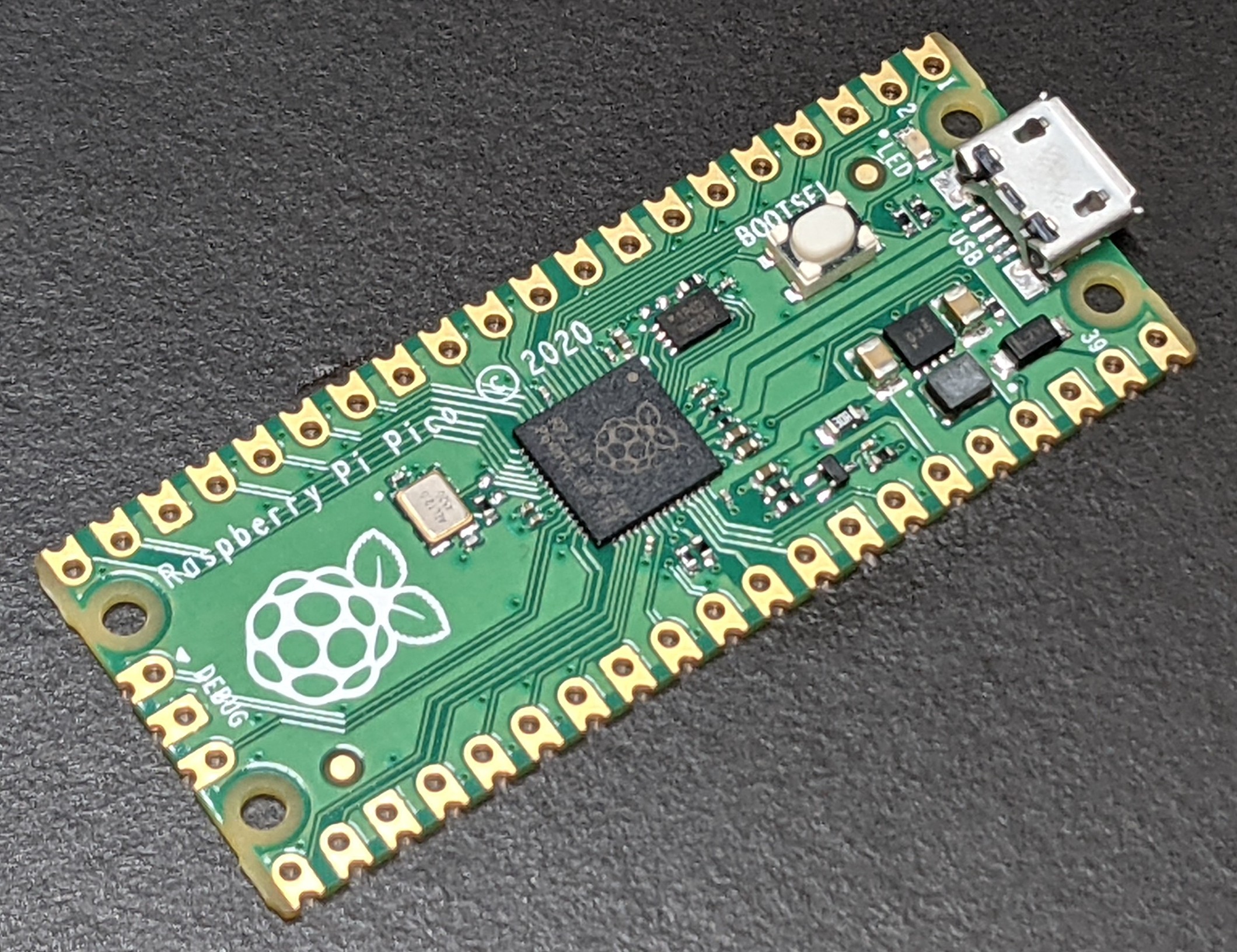
It’s okay if someone else has made a sort of similar board, but yours should be a new design. For example, there are 9 different boards available from Pimoroni, but mostly, the field is wide open. Also, there are new sensors and other chips coming out every day. Ask your non-engineer friends what magical device they wish they had; build the closest approximation you can.
In thinking through ideas, you might investigate the Pico’s PIO modules. These are special chunks of silicon embedded in the Pico’s processor that can be programmed in a 9-instruction assembly language to implement lots of weird digital protocols spoken by different sensors or actuators.
Let’s be clear about what the goals are here. If you have never made a PCB before, your goal should be to submit a PCB before the due date where at least the components you think you need can be soldered to the board– think of it as a first draft. If you have made several PCBs before, you should aim to make something that actually works, though it’s hard to get every detail right on the first try.
A few detailed requirements:
- Please use Kicad to design the PCB.
- For fabrication, please use OSHPark. They’re reasonably cheap and have successfully delivered over 100 PCB orders to Tufts with zero mistakes.
- Your PCB should almost certainly use two 1x20, 0.100” pitch header sockets. I have ordered a pile of them, so we can get them more cheaply ($0.19 each direct from China via Ebay, instead of more like $1.20, with shipping amortized across 35 people, but we have to wait a few weeks).
A note about programming:
This class will be mostly about programming microcontrollers. But, around 90% of you are really excited to make PCBs that enable new programming opportunities. PCB fabrication takes a while, so we have to get the PCB out the door first. We’ll mostly focus on programming after this first project, but we’ll also do a second revision of this board as one of the later projects.